Fans of the reality series, The Great British Baking Show, are likely familiar with a segment called the “technical challenge.” Contestants are asked to bake a specific creation of the judges’ choice using a sparse recipe that omits a single key piece of direction. This task leads to frantic contestants guessing what the final baked item is supposed to look like and what key direction was left out. While the contestants throw ingredients together, we eat our popcorn at home, entertained at their expense, knowing that they are in for a big surprise when they hand in their bake to the steely-eyed host, Paul Hollywood.
Unfortunately, this is how we sometimes feel as architects watching a contractor struggle to deduce what our elaborately designed cake is supposed to look like. We spend months working in sophisticated three-dimensional models, creating photo-realistic images to help clients visualize our designs. However, these straightforward, visually compelling images can exist in sharp contrast to the technical drawings that we provide to contractors to build our designs.
Despite technological advancements that allow architects to produce drawings faster and more accurately than ever, the actual set of printed drawings provided to contractors mostly has gone unchanged over the last 50 years. How do we advance beyond providing contractors a complicated recipe of two-dimensional drawings and expecting that they will fully understand our vision? At BBT, we believe that it starts by sharing a photo of the finished cake.
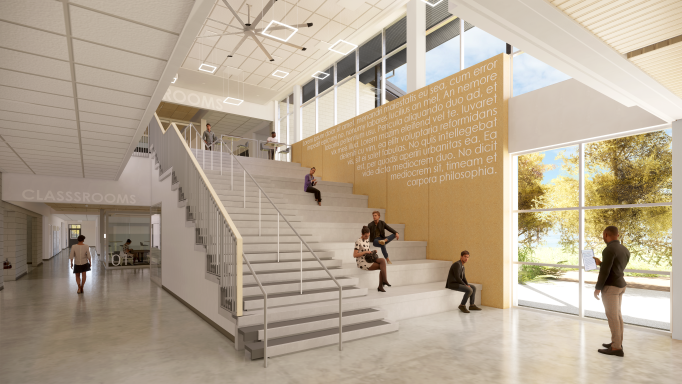
Real-time rendering software has proliferated throughout the design industry, allowing designers to create near photo-realistic imagery almost in an instant.
This technology not only allows us to design three-dimensionally in real-time, it also enables us to virtually walk clients through their future spaces. For anyone without formal training in reading architectural plans, sections, and details, these tools portray designs in the same way that most people see and interact with their daily surroundings. Our internal design teams often use the same rendering programs to visualize complex building systems to check for conflicts among structural systems, mechanical ductwork, and piping configurations. For even the most experienced architects and engineers, seeing the relationship between components has resulted in finding conflicts sooner, leading to thought-out solutions before a contractor even reviews a drawing.
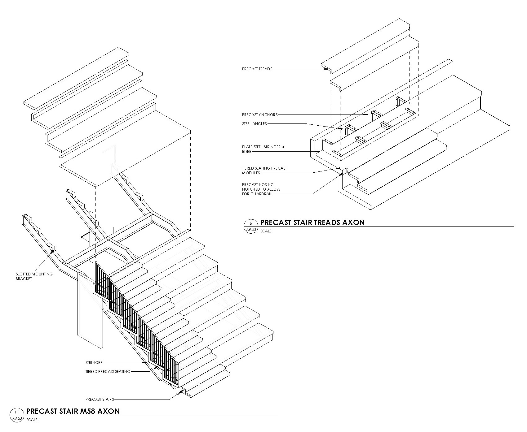
In addition to illustrative renderings, one of the greatest tools at our disposal is the ability to create three-dimensional “axonometric” details. These drawings can communicate how various components meet in three-dimensional space. They also convey technical information that wouldn’t normally be included in a rendering. When paired with a standard two-dimensional drawing, this unique format describes difficult concepts such as sequencing, overlapping layers, and terminations. We see these details as the best of both worlds; they contain technical information, show the relationship between components, and sometimes can even be nice to look at. You could say it’s like having your cake and eating it, too.
Using different tools and methods to convey the intention of our design also creates a more balanced team relationship with the contractor. Through renderings, three-dimensional diagrams, and virtual environments, the architect’s process helps inform and involve the contractor and opens doors to collaboration. Our goal is to provide builders with a recipe and a photo, because while it’s good fun to watch someone’s cake fall apart, it’s much sweeter when the cake comes together just as you planned it.
By Kyle Burke and Bennett Sapin


